QS18-12辉光钟.黄金纪念版.GPS校时.二十四小时的感动(古典版IV)【严泽远作品】
做过那么多时钟,为什么还是喜欢辉光管?原因其实很简单,它上面刻有历史…
或许您对电子管没有一点感情,也或许您见到的第一台数字电子时钟就是现代科技造就的LCD,LED甚至VFD…但透过久远的岁月,重温那时的一点一滴,想象一下没有大规模集成电路的时代,想象一下没有手机、没有网络、甚至无线电视信号也就只能收到中央电视台的时代,辉光管也只有在军队的电子装备上能够见到…
很多朋友第一眼见到辉光管,即评价:这个灯很耗电吧…其实一点也不意外,毕竟了解辉光管的朋友不多,甚至大多数人都还认为这里面是灯丝通电发热才显示,其实,辉光管工作的时候根本就不发热,1mA的电流即可点亮,相当于170mW的功率,几乎不怎么有功耗。
最喜欢辉光管的有三点:
首先它显示数字很有层次感,所有数字前后错落有致,从稍侧面看去,层次感极强。
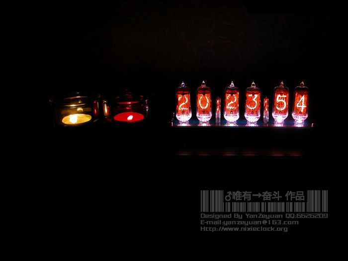
其次就是辉光的那种温暖的橘红色光芒,尤其是在夜晚,朦胧之下给人温馨之感。
再次就是字体的形状,LED,点阵都无法与其媲美,毕竟每个字都是一片专门的金属制作而成,独特的完整的字形,类7段显示的模式都无法抗衡。
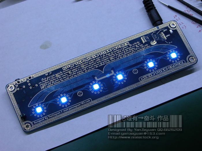
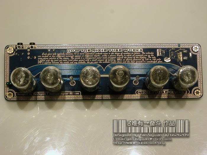
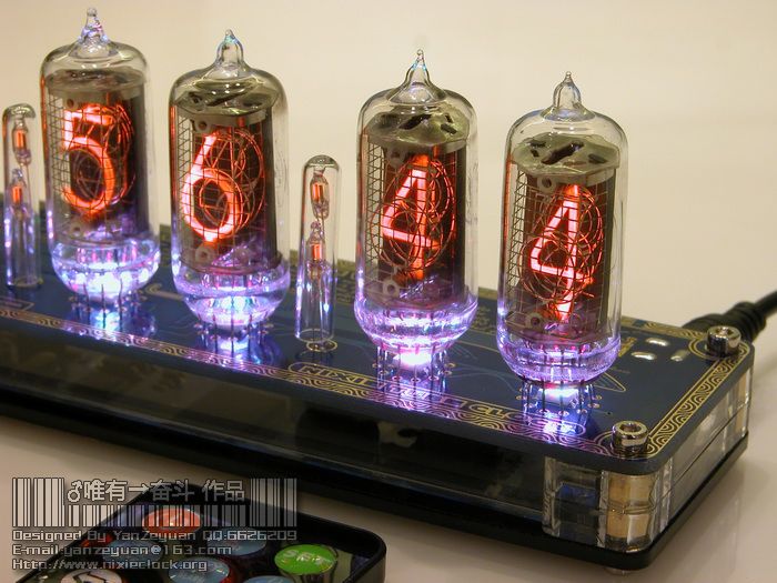
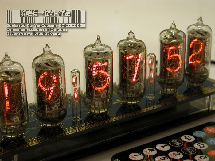
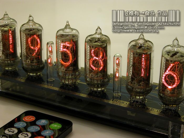
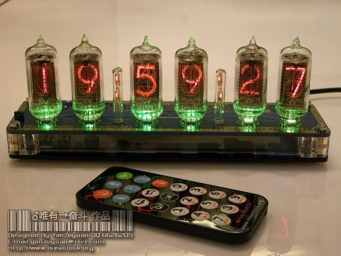
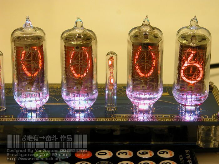
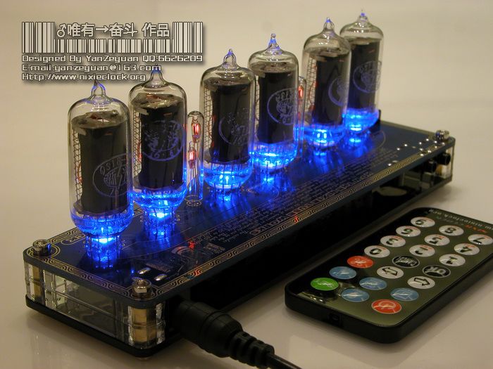
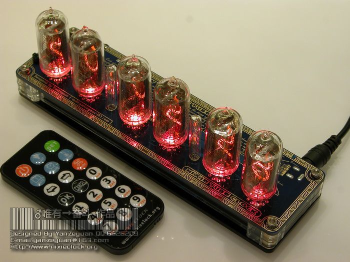
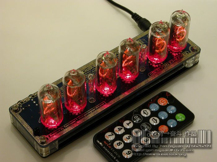
言归正传,QS18-12是70-80年代中国造最大尺寸的侧显辉光数码管,当然,现在这个型号的辉光管已经濒临灭绝,是极其罕有之物,在辉光管当中,其实又分为顶显与侧显,侧显的管身直立,更有电子管的味道,所以备受亲睐。这次的QS18-12管子也非常非常少,物以稀为贵,为了能够匹配这稀缺的具有历史意义的QS18-12辉光管,历时两个多月的筹划与设计,QS18-12黄金纪念版辉光电子时钟正式揭开它的神秘面纱,先来几张大图秀一秀:
=-=-=-=-=-=-=-=-=-=-=-=-=-=-=-=-=-=-=-=-=-=-=-=-=-=-=-=-=-=-=-=-=-=-=-=-=-=-=-=-=-=-=
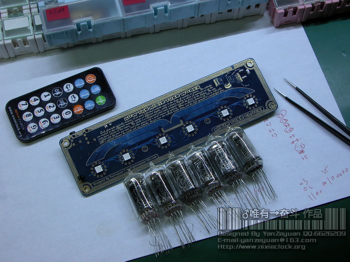
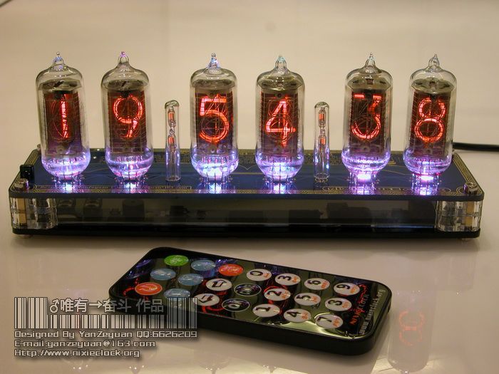
既然是黄金纪念版,但看起来与以前的QS18-12辉光钟貌似没有太大区别,其实不然,第一张图上的全家福已经揭示了她具有非凡的功能:
1、 6位数字辉光管显示日期(年月日)和时间(时分秒);
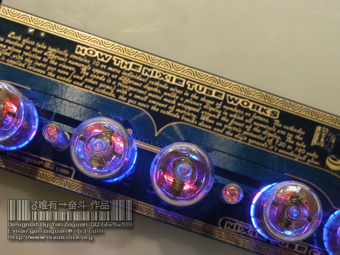
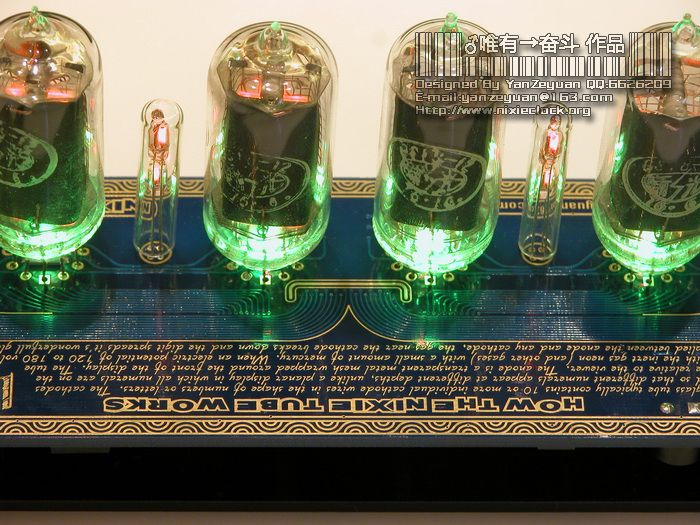
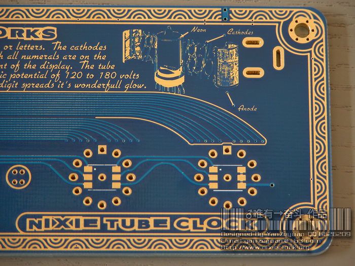
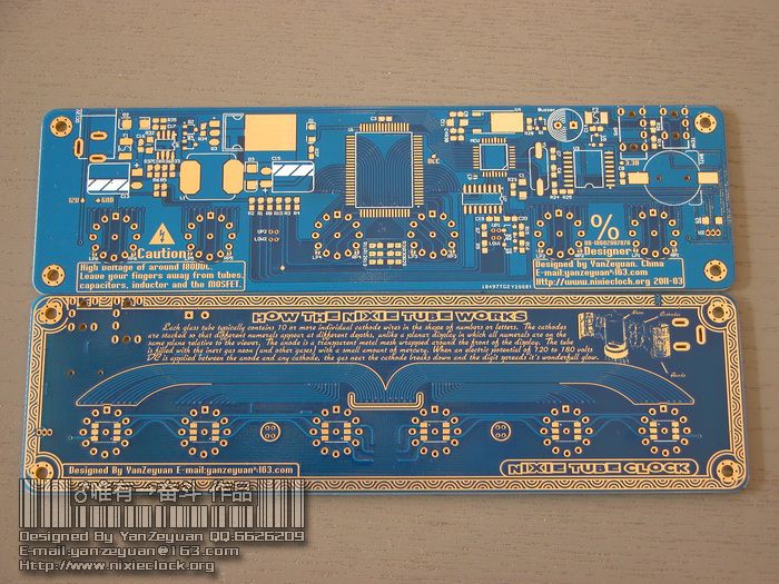
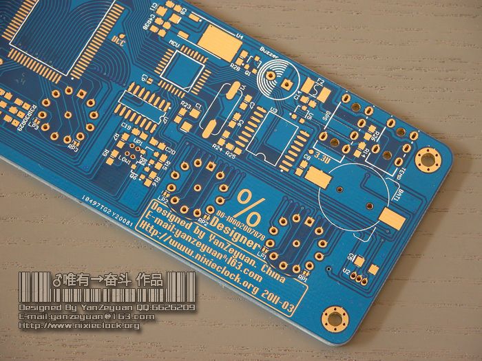
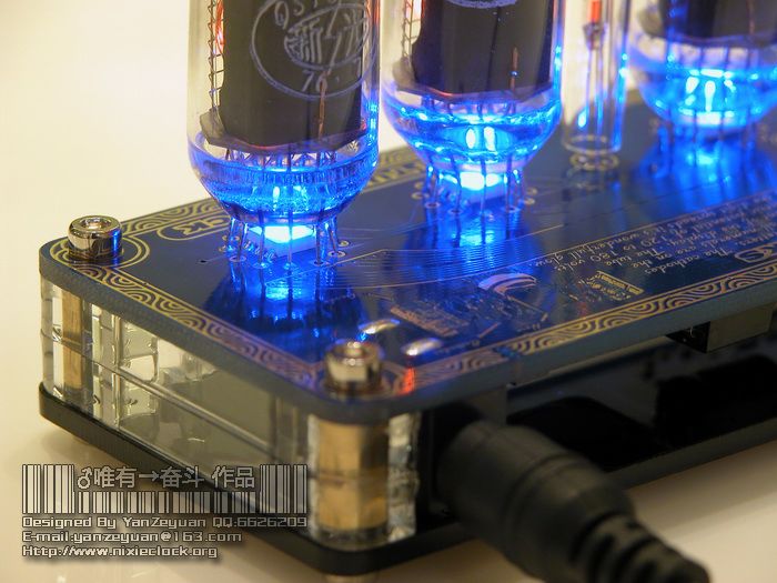
2、 PCB板厚2.0,沉金工艺处理,艺术花边效果,内嵌How The Nixie Tube Works原版英文镀金叙述及辉光管原始解剖图,颇具收藏价值;
3、 单芯片集成工艺,一颗IC直接驱动6颗辉光管,性能稳定可靠;
4、 红外线遥控控制所有功能,时钟本身无按键,简洁大方;
5、 GPS自动校时功能,支持手动启动GPS校时,可选外接GPS模组;
6、 内置GMT时区设置功能,并集成格林尼治时间自动换算当前时区日期时间的算法,断电记忆时区设置,无需担心准确度问题;
7、 四种辉光数字切换效果:Crossfade.Fadein and fadeout. Flipover. Standard;
8、 4只3毫米直径氖灯组成双冒号,呼吸效果指示;
9、 两组闹钟功能,可分别设置不同时间,可分别启用或关闭;
10、 室内室外温度显示功能,可选配室内或室外温度传感器;
11、 具备摄氏度/华氏度温度单位切换功能;
12、 支持断点保存温度单位设置,无需再切换温度单位;
13、 配备12v全球通用的电源适配器;
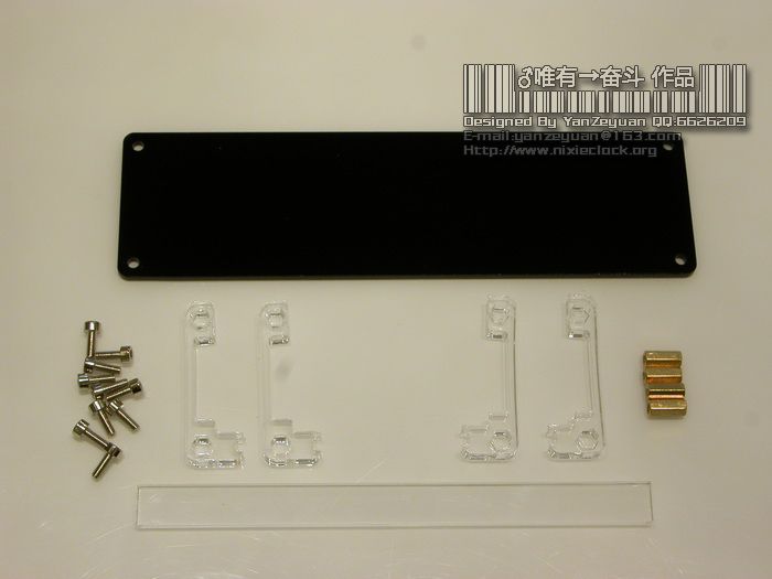
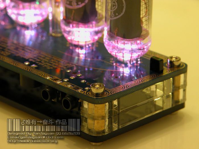
14、 激光切割亚克力底座+不锈钢内六角螺丝,彰显沉金工艺电路板特色;
15、 采用DS3231高精度时钟芯片,内置温补晶振,走时精确,年误差1分钟以内;
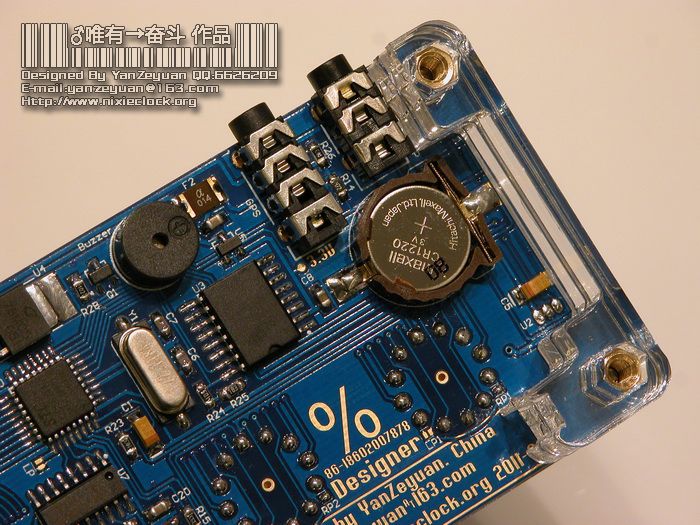
16、 内置锂电池,断电5年仍旧能够自动计时;
17、 RGB全彩背景光显示,可手动切换背景光显示模式,手动选择色彩,或关闭背景光功能;
18、 支持公历日期显示和中国农历日期显示;
19、 具备YY.MM.DD日期格式和MM.DD.YY日期格式选择;
20、 支持断电保存日期格式设置,无需再切换格式;
21、 支持12小时及24小时时间格式;
22、 支持断电后自动记忆时间格式,无需再切换时间格式;
23、 支持“赤橙黄绿青蓝紫”代表周一至周日的色彩星期指示功能;
=-=-=-=-=-=-=-=-=-=-=-=-=-=-=-=-=-=-=-=-=-=-=-=-=-=-=-=-=-=-=-=-=-=-=-=-=-=-=-=-=-=-=
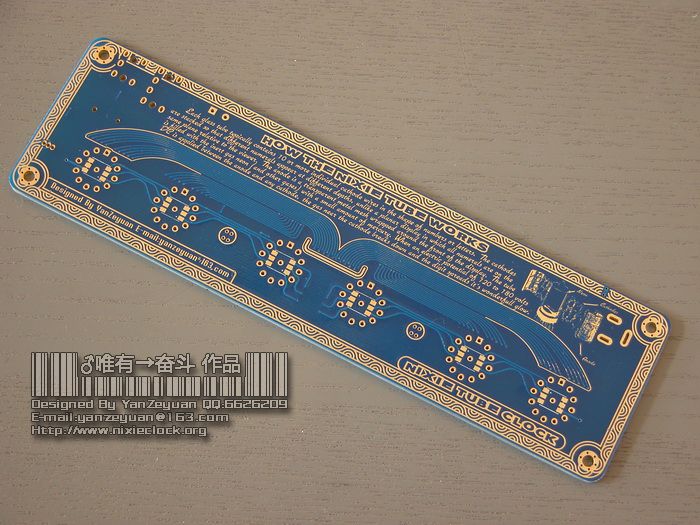
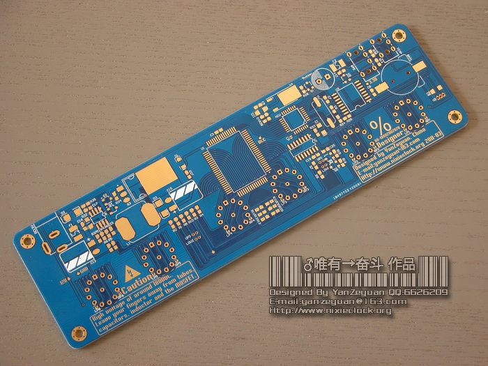
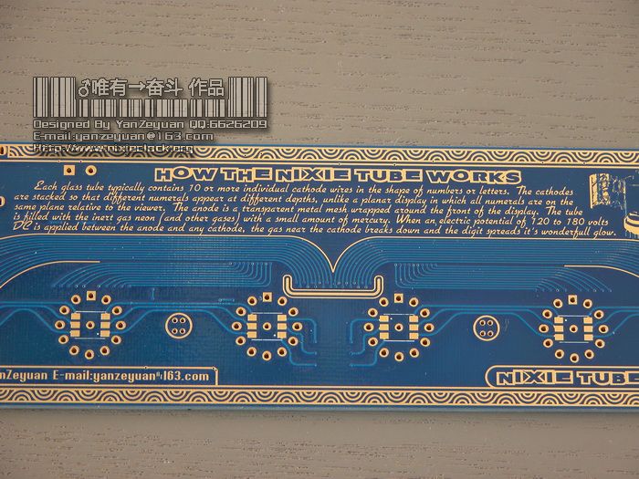
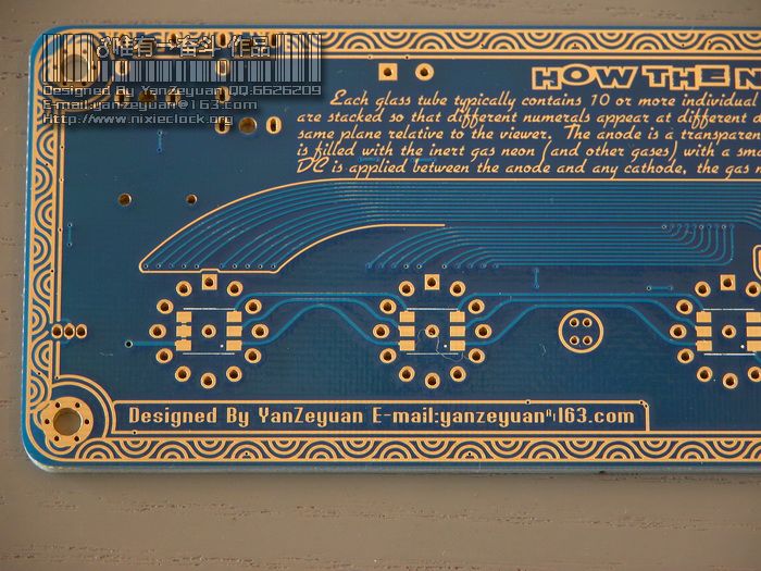
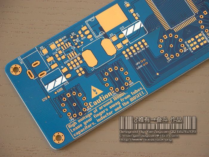
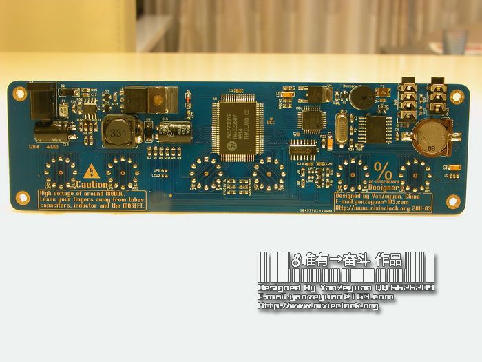
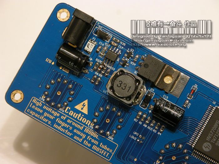
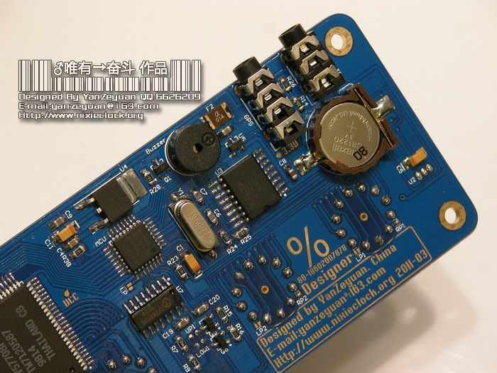
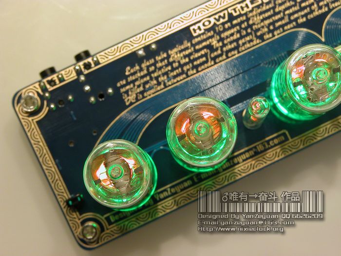
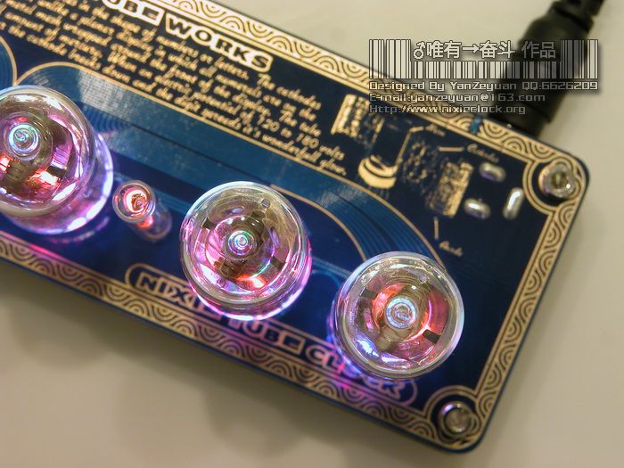
先看一下这次的PCB板,继续采用2.0板厚的沉金工艺板,外加精心设计的花边,利用线路本身的Track,在Top Layer绘出一本掀开的书,书的边缘用沉金线条勾勒。在书的上面,题写了HOW THE NIXIE TUBE WORK,英文原版介绍资料,揭示辉光管是如何工作的。原文如下:
HOW THE NIXIE TUBE WORKS
Each glass tube typically contains 10 or more individual cathode wires in the shape of numbers or letters. The cathodes are stacked so that different numerals appear at different depths, unlike a planar display in which all numerals are on the same plane relative to the viewer. The anode is a transparent metal mesh wrapped around the front of the display. The tube is filled with the inert gas neon (and other gases) with a small amount of mercury. When an electric potential of 120 to 180 volts DC is applied between the anode and any cathode, the gas near the cathode breaks down and the digit spreads it’s wonderfull glow.
在PCB板Top Layer右上角,沉金绘制了一只分解开的辉光管的示意图,形象的标注了哪部分是Neon,哪部分是Cathodes,哪部分是Anode。
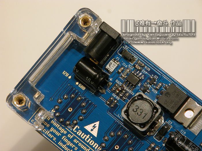
Bottom Layer还用文字注明了注意事项,谨防高压危险。
=-=-=-=-=-=-=-=-=-=-=-=-=-=-=-=-=-=-=-=-=-=-=-=-=-=-=-=-=-=-=-=-=-=-=-=-=-=-=-=-=-=-
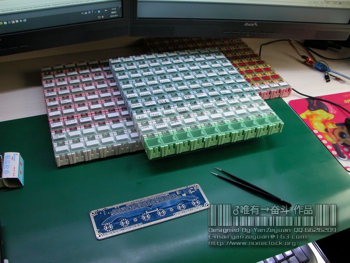
准备开工了…
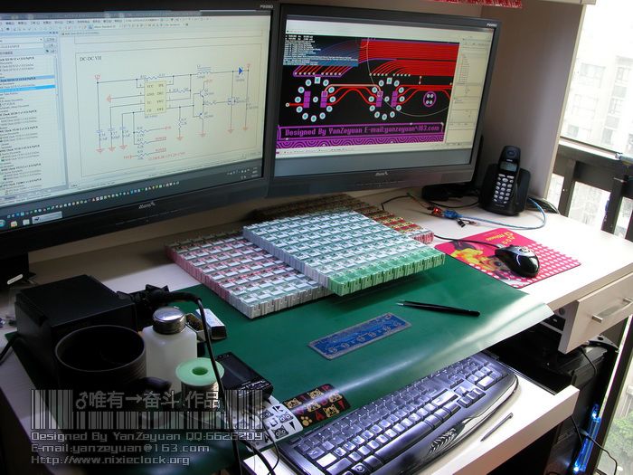
开工之前准备好所有工具和元器件…
=-=-=-=-=-=-=-=-=-=-=-=-=-=-=-=-=-=-=-=-=-=-=-=-=-=-=-=-=-=-=-=-=-=-=-=-=-=-=-=-=-=-
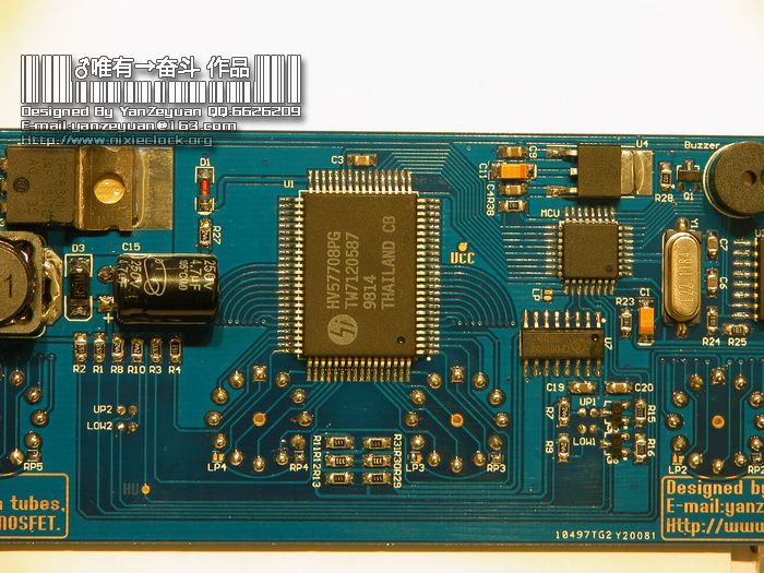
整个辉光钟的组装过程比原先要快很多,因为这里我采用了一颗非常专业的高速高压驱动IC,HV57708,它具备64个高压输出端口,32Mhz的通讯速率,能够配合程序完成任何数字切换特效,外围器件简单,比起原来60个A42三极管+60颗33K电阻+8颗74HC595芯片要集成度高出很多,但是这款芯片的价格非常昂贵,原装正品大概11美金/片,可谓是高端硬件配置了,国内做辉光钟的静态驱动没有如此简洁的设计。
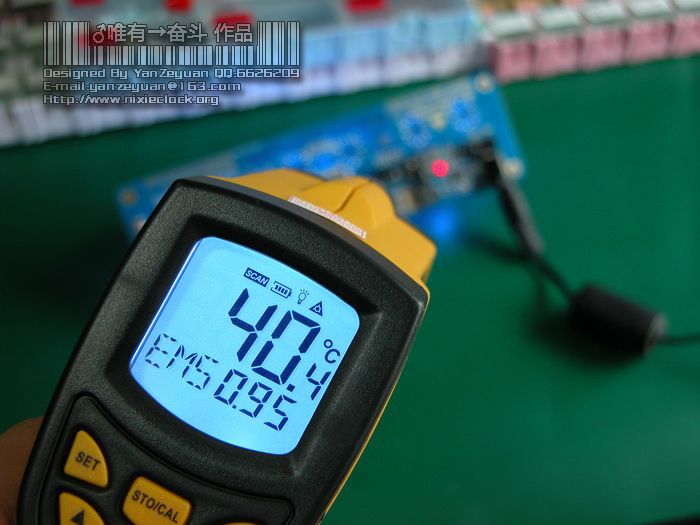
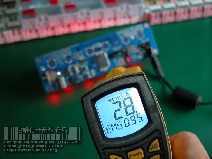
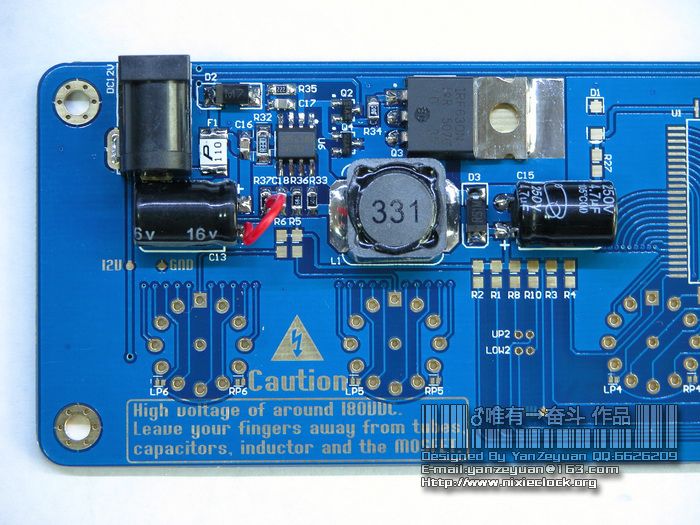
其他部分也做了适当调整,升压部分采用了双对管推动MOS,效率有大幅度提升,MOS管和电感的温度较前两款辉光钟有明显下降:
=-=-=-=-=-=-=-=-=-=-=-=-=-=-=-=-=-=-=-=-=-=-=-=-=-=-=-=-=-=-=-=-=-=-=-=-=-=-=-=-=-=-=
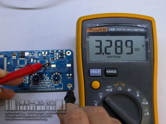
整个装配过程还是依照电源部分优先的原则,将三级电源模块全部从高往低组装调试通过以后再焊接其他部分。
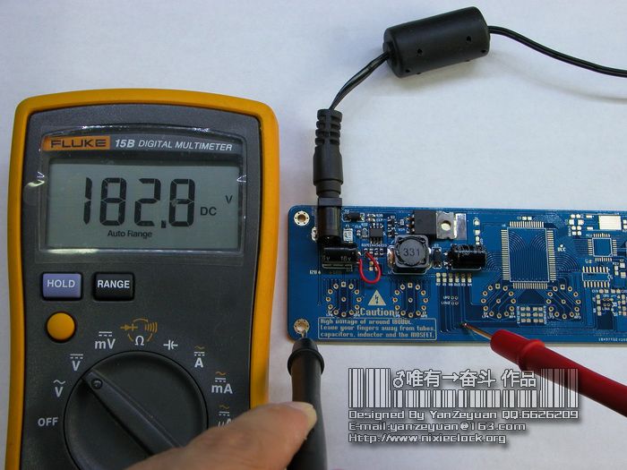
首先是辉光管的高压部分,这次选用了比170v电压稍高的高压电压值182V。
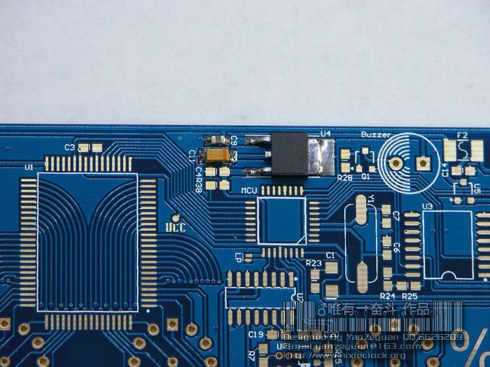
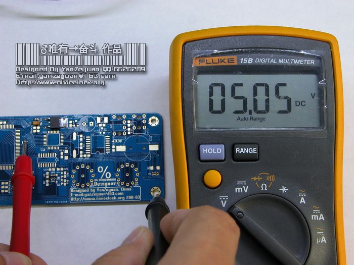
然后是MCU和罗技芯片的5V供电模块部分。
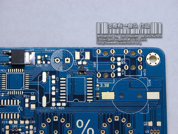
最后是DS3231工作使用的3.3V供电模块部分。
将这三组电源模块组装通过,剩下的元器件就可以全部焊接上去了。
整个过程如下:
=-=-=-=-=-=-=-=-=-=-=-=-=-=-=-=-=-=-=-=-=-=-=-=-=-=-=-=-=-=-=-=-=-=-=-=-=-=-=-=-=-=-=
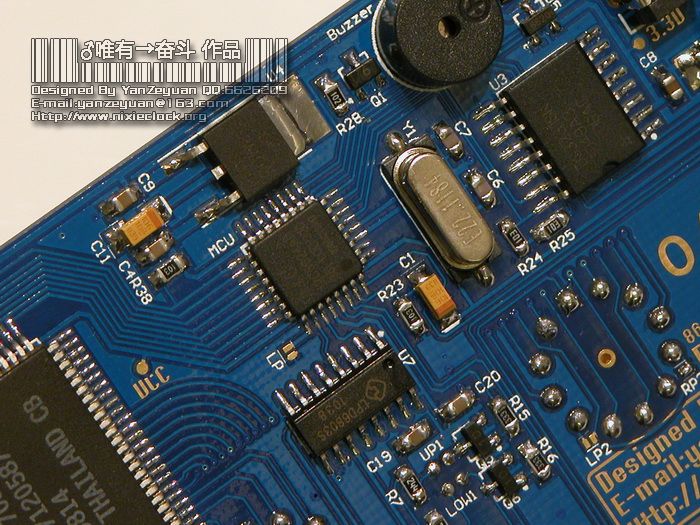
这里特别要说明的是,我在设计之初,就考虑到了国产QS18-12有两种管教封装的问题,所以专门在辉光管的焊接焊盘附近设计了两个选择断点,如下图:
如果是左点的QS18-12辉光管,就将LP断点短路焊接,如果是右点的QS18-12辉光管,就将RP断点短路即可。
由于左点和右点的辉光管管脚排列不同,数字的显示位置也不同,所以程序有所区别,所以设计的时候,我在MCU旁边放置了一个断点选择,如果是左点的QS18-12辉光管,MCU旁边的这个LP需要被短路焊接。
=-=-=-=-=-=-=-=-=-=-=-=-=-=-=-=-=-=-=-=-=-=-=-=-=-=-=-=-=-=-=-=-=-=-=-=-=-=-=-=-=-=-=
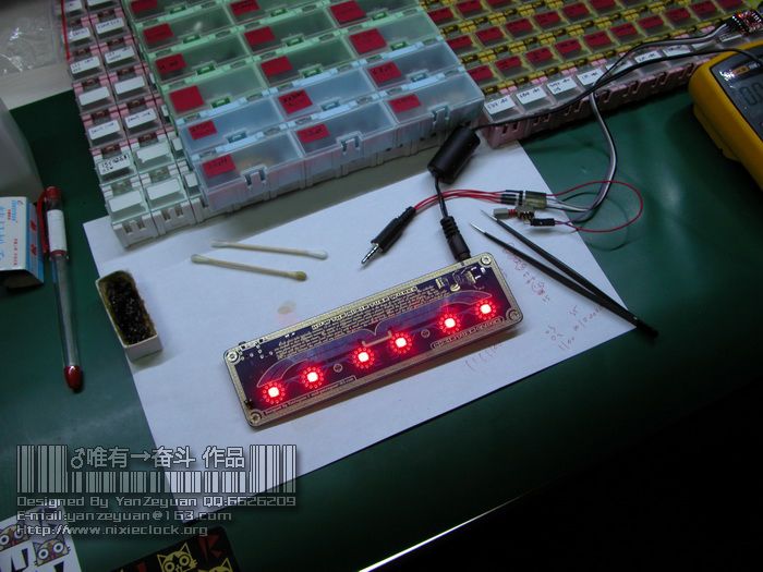
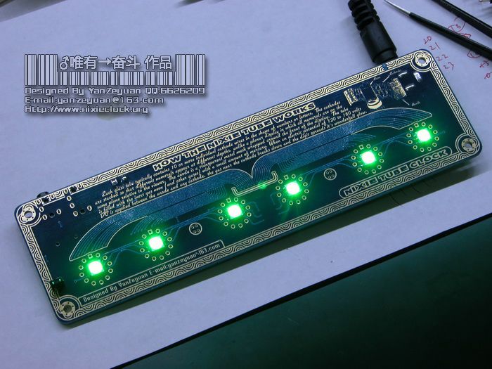
上次的QS18-12辉光钟选用了冷白色的LED做背景灯光源,并且用PWM技术实现了呼吸效果,但是有些朋友问我有没有蓝色的背景灯光,有些朋友问我有没有黄色的背景灯光,还有人问我能否关闭背景灯光……
看来众口难调啊,所以本次设计直接采用了5050的RGB LED来做背景灯光源,采用了专用的RGB LED驱动芯片,PWM模式下能够实现全彩背景灯控制。
当然,如果喜欢红色,黄色,蓝色或绿色紫色等等,可以直接通过遥控器选择相应的背景灯灯光颜色即可,也可以选择七彩自动呼吸切换模式,还有最新制作的“赤橙黄绿青蓝紫”七种颜色代表周一至周日一共七天的彩色星期指示模式。
=-=-=-=-=-=-=-=-=-=-=-=-=-=-=-=-=-=-=-=-=-=-=-=-=-=-=-=-=-=-=-=-=-=-=-=-=-=-=-=-=-=-=
温度显示功能还是必不可少,平时可以了解室内或室外温度。以往设计的几种辉光钟、VFD荧光钟,都在温度传感器的应用方面忽略了一些小小的细节。
其实DS18B20很好用,但是要注意如果使用DS18B20的话,一定要将其远离发热源,包括PCB本身。以往做过的QS30-1辉光钟、QS18-12辉光钟,包括YS18-3荧光电子管时钟,我都把DS18B20装在了电路板上,这样,虽然DS18B20的管身露在外面,但是PCB本身是要发热的,热量会通过DS18B20的三个金属管脚直接传导到管子里,往往温度会比实际温度高出好几度。
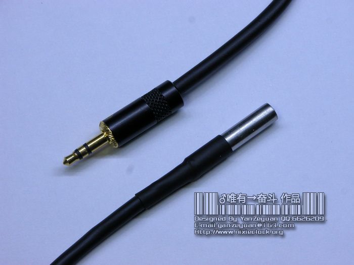
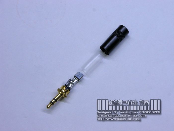
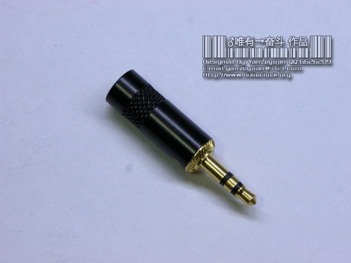
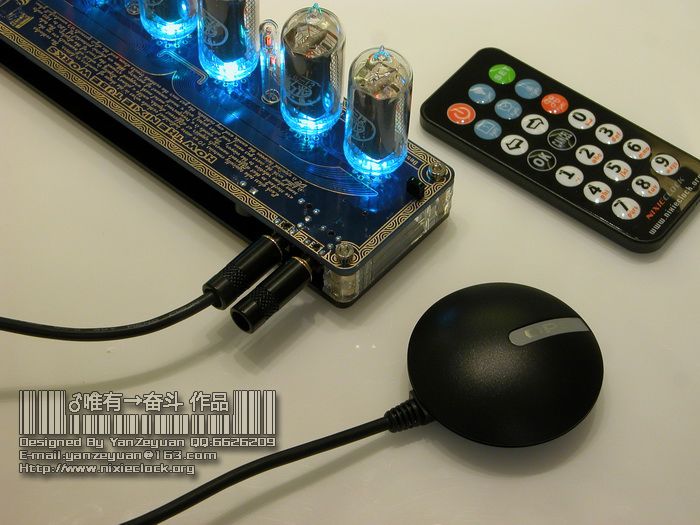
所以这次专门为温度传感器设计了可插拔的接口,使用3.5的耳机插头连接DS18B20温度传感器。而且使用了高质量的3.5耳机插孔和全金属的高档镀金耳机插头。
看一下,这是用于室内温度探测的外置温度传感器,其实就是在3.5mm耳机插头里内置了一颗DS18B20温度传感器,做好了样子还是不错的,而且杜绝了温度不准的问题。
=-=-=-=-=-=-=-=-=-=-=-=-=-=-=-=-=-=-=-=-=-=-=-=-=-=-=-=-=-=-=-=-=-=-=-=-=-=-=-=-=-=-=
将温度传感器做成插孔外接方式还有一个好处,就是可以将温度传感器拉出室外,用于测试室外温度。
曾经有一位朋友就问过我好多次,能不能显示室外温度,其实将DS18B20飞线飞出室外就可以了,但是原先的辉光钟、荧光钟,都需要自己动手改造,这次直接用1米线长或者3米线长的带不锈钢探头的DS18B20温度传感线就可以了。
既然是可插拔的,如果温度传感器未插上会有什么结果?在以前设计的QS30-1和QS18-12辉光钟上,如果不焊接DS18B20并且按下遥控器上的TEMP键查看温度时,时钟会死机,因为它在不停的等待DS18B20的回复,其实这是一个不合理的程序模块,这次在黄金纪念版上,我采用了检验和初始化模块,能够迅速判断是否装有DS18B20温度传感器,如果未装传感器,时钟会快速退出温度显示状态。
看一下效果,插头依然采用镀金的3.5mm全金属耳机插头:
=-=-=-=-=-=-=-=-=-=-=-=-=-=-=-=-=-=-=-=-=-=-=-=-=-=-=-=-=-=-=-=-=-=-=-=-=-=-=-=-=-=-=
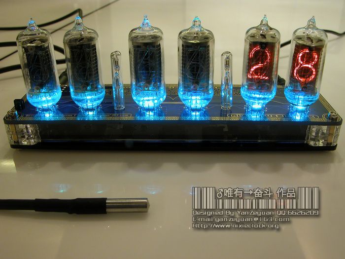
看一下温度采集时的温度显示功能:
=-=-=-=-=-=-=-=-=-=-=-=-=-=-=-=-=-=-=-=-=-=-=-=-=-=-=-=-=-=-=-=-=-=-=-=-=-=-=-=-=-=-=
这次的辉光钟与以往最大的不同是具备了GPS校时功能。
准确度是时钟最首要要解决好的问题,也是最基本的功能,功能再丰富,效果再花哨,走时不准就失去了作为时钟的最原始意义。
其实有很多校时的方式:电波、GPS、网络、GSM等等……
每种校时方式都有其特点,当然,最准确的就属GPS对时了,理论上能够达到30nS,但是我们平时使用误差在100ms就足足能满足需求。但是GPS对时有一个不方便的地方,就是GPS需要在露天的地方才能接收到信号,或者在窗边。
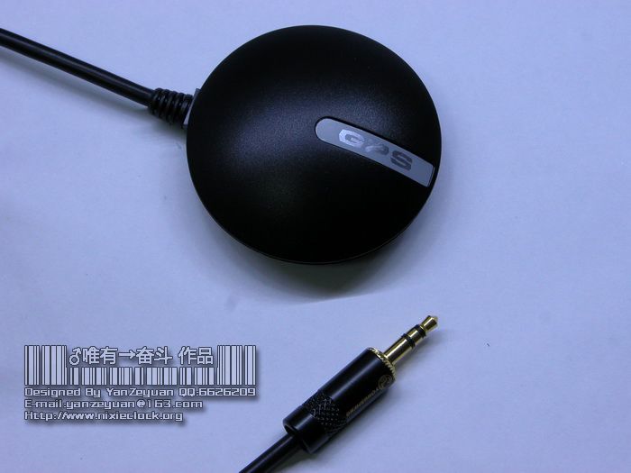
这次选用的GPS接收机是台湾的一款室外防水的带磁吸附底座的GPS接收机,它采用SiRF Star III代技术,-159dBm的灵敏度,采用NEMA0183通讯协议,其实我在这里只是使用了简单的获取卫星精确格林尼治时间的功能。
这款GPS接收机是RS232接口的,需要转换为TTL电平信号,通过时钟的MCU串口进行通讯。
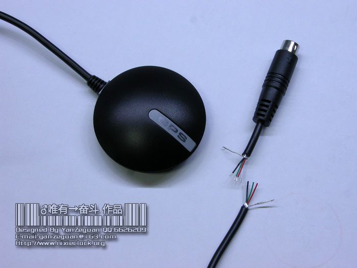
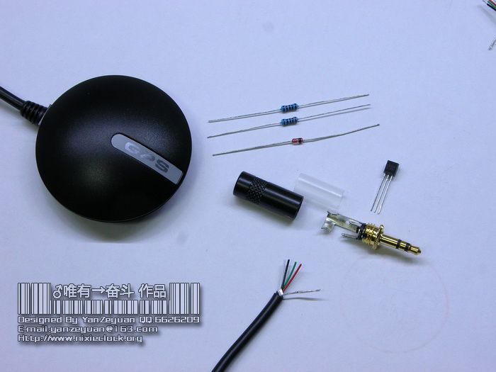
原本GPS接收机自带的是PS/2的标准接口,由于需要使用TTL电平信号,所以我给GPS接口动了点儿小手术:把PS/2接口剪掉,依旧使用3.5mm的标准耳机插头。
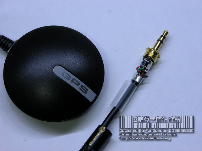
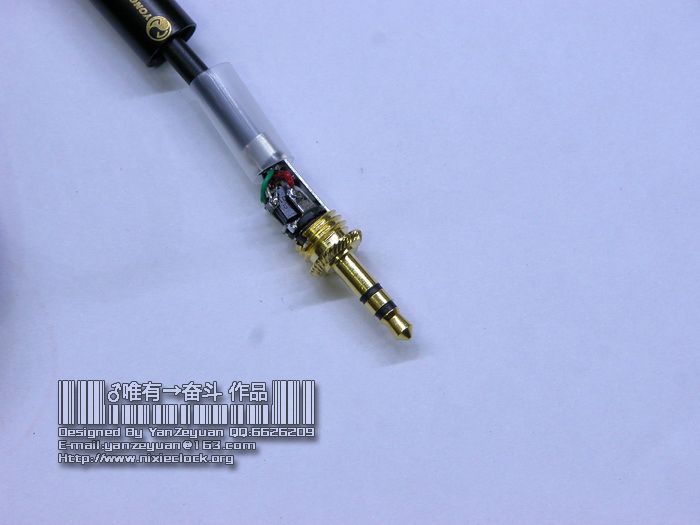
值得一提的是,原本需要一颗MAX232或者SP3223等等这些RS232转TTL电平的专用芯片来转换数据接口类型,我只使用了一颗三极管,两颗电阻,一颗二极管完成RS232-TTL的简单转换,并且把它们都塞到了一颗金属的3.5mm耳机插头里面,请看制作过程:
=-=-=-=-=-=-=-=-=-=-=-=-=-=-=-=-=-=-=-=-=-=-=-=-=-=-=-=-=-=-=-=-=-=-=-=-=-=-=-=-=-=-=
GPS接收机获取的不是当地时间,而是格林尼治标准时间,也就是说如果我们的位置在不同的时区,需要进行相应的时间换算。
原来,我忽略了这个问题,认为这个换算格林尼治时间很简单,无非是加减小时的问题,但是其实这个换算算法还是值得认真思考的。
比如说,大家都知道,北京时间是GMT+8的时区定义,如果我获取到了一个时间信息是格林尼治时间2011年3月31日20点整,那么北京时间应该是多少呢?有些朋友会说,时间+8就行了啊,是的,没错,如果单纯算时间,就是加减的问题而已。但是牵扯到日期,就需要判断是否闰年,是否大月小月的问题了。复杂倒不是很复杂,但是陷阱很多,弄不好日期会不准确。
我在数码之家发了一篇帖子,专门讨论格林尼治时间换算各时区的时间的算法,并且贴上了源代码:
http://www.mydigit.net/read.php?tid=249841
比如从GPS里读出了一条命令:
$GPRMC,105404.739,A,2307.5573,N,11323.3638,E,2.65,348.60,040411,,,A*65
提取出来格林尼治时间是:
2011-04-04 10:54:04.739
换算成北京时间+8是18:54:04.739 很简单,没啥问题。
但是晚上又读到一条命令:
$GPRMC,213201.236,A,2307.5573,N,11323.3638,E,2.65,348.60,040411,,,A*65
换算成北京时间就不是简单的+8的问题了,差点儿疏忽,不然会差很远。
算法搞定了,我们就能根据获取的GPS标准格林尼治时间,来得到世界上各个时区的时间,所以在这次黄金纪念版辉光钟上,还可以自行设置用户所在的GMT时区,设定好时区以后,GPS对时的时候会自动根据格林尼治时间换算当地时间。
手动启动GPS对时的时候,背景灯会快速的闪烁红色,一般GPS正常工作的时候,会在20秒内获取到正确的GPS卫星标准时间,并重新调整时钟日期和时间。
除了手动启动GPS对时的功能以外,我还在程序里设定了每周一早8:00,自动启动GPS校时功能,这样下来,想不准都难。
GPS是可以插拔的,如果没有连接GPS设备的时候,启动自动对时的时候,时钟会自动检测到GPS不存在,并快速退出对时模式。
=-=-=-=-=-=-=-=-=-=-=-=-=-=-=-=-=-=-=-=-=-=-=-=-=-=-=-=-=-=-=-=-=-=-=-=-=-=-=-=-=-=-=
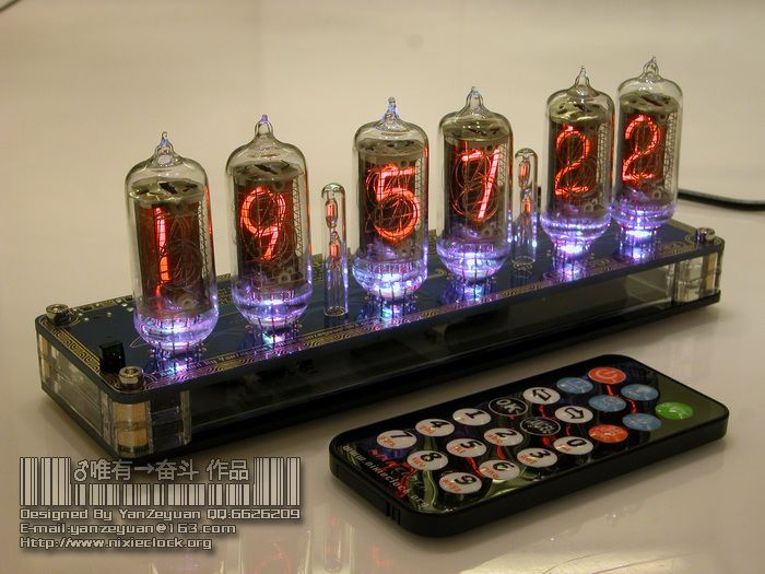
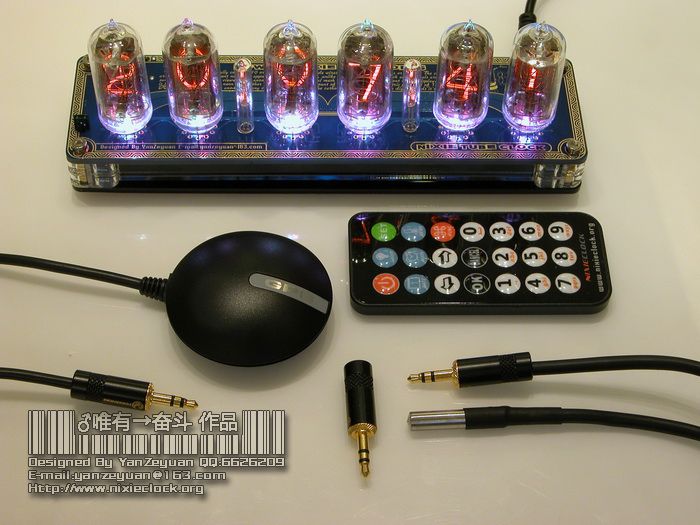
秀一下全家福,和温度传感器和GPS接收机均插在时钟上的样子:
一共包括:
1、电源适配器;
2、红外线遥控器;
3、辉光钟;
4、GPS接收机;
5、室内温度传感器;
6、室外温度传感器;
=-=-=-=-=-=-=-=-=-=-=-=-=-=-=-=-=-=-=-=-=-=-=-=-=-=-=-=-=-=-=-=-=-=-=-=-=-=-=-=-=-=-=
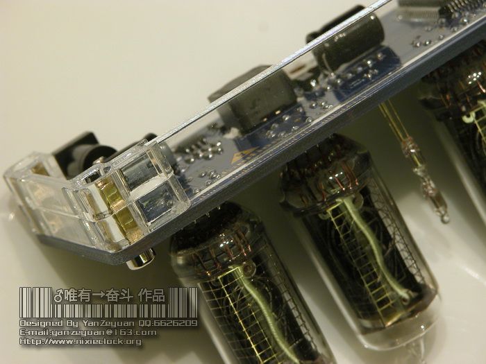
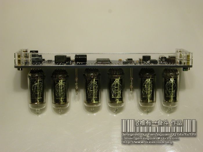
这次黄金纪念版辉光钟的PCB经过精心的设计和布板,黄金线条边衬托辉光管放射出令人遐想的古典味道,所以在外壳方面,我考虑了很多种很多种方案。
考虑过全裸,但是能触摸到电路板元器件毕竟不安全,内部的180V高压虽然电流很小,但是还是会让人感觉到被大螃蟹夹住的刺痛感。也考虑过用木盒,或者用铝合金拉丝加阳极氧化的工艺把辉光钟包裹起来,但后来觉得精心设计的PCB被包裹起来,枉费了一番精心创意,所以后来考虑用激光切割的亚克力板,做一个底座。
先用CAD绘制精确的图纸,然后交给激光亚克力加工厂,很快,精确的亚克力外壳被切割出来。
下面是黄金纪念版外壳的所有部件合照,还有安装的细节:
=-=-=-=-=-=-=-=-=-=-=-=-=-=-=-=-=-=-=-=-=-=-=-=-=-=-=-=-=-=-=-=-=-=-=-=-=-=-=-=-=-=-=
至此,最后一版QS18-12辉光电子管时钟,全部完工,因为这种管子已经近乎绝迹,所以以后也不打算再做这种管子配套的时钟了,自己留在家里作为收藏品。
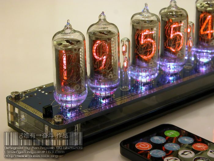
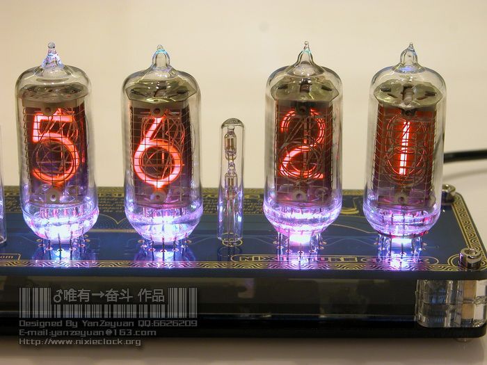
下面送上一些细节的特写和全部美图,希望朋友们能喜欢。
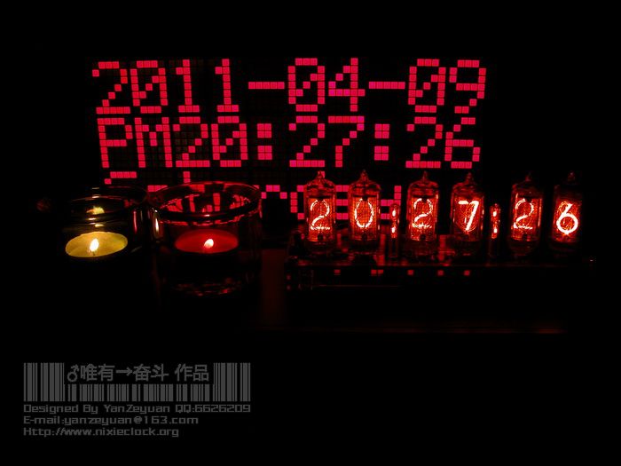
对了,还有跟我两年前作的LED点阵日历钟的合照,呵呵;-)
DIY是一种享受,享受的是过程,更是结果……
========================================================
作者:严泽远
QQ:6626209
2011-04-10



25 条评论
Joachim Beck · 2012 年 1 月 29 日 上午 5:29
Dear Sir,
you are making fantastic Nixieclocks and I am very interested to get THISS ONE (QS18-12).
Tell me what to do.
Thank you in advance.
Kind regards,
Joachim Beck
scaleo1112
♂唯有→奋斗 · 2012 年 1 月 30 日 下午 5:07
Hi Joachim,
Thanks for your visit, It’s my pleasure that you like my clock.
But unfortunately, the last one was sold on eBay at last month, so it’s out of stock now.
I have designed some kinds of tube clocks, inlucde VFD tube clock, NIXIE tube clock and LED clock, the most popular is NIXIE clocks.
Please keep your eyes on my Blog, I’m going to build some other type of NIXIE clocks, maybe you will like.
Any questions let me know.
Thanks and regards.
Yan.
Ilya · 2012 年 2 月 8 日 上午 7:37
Hello,
i want to buy one VFD Graphic clock.
I found your site through e-bay, and i really interested with your devices.
I like electronic, i know a lot about it but in russia there is no easy way out to craft such devices.
I will be very glad to co-operate with you.
I have some ideas about electronic devices.
Write me to my email psy21d@gmail.com (english).
I am in skype online psy21d. (or i can to go to QQ if you are online)
I am waiting for your reply.
Regards,
Ilya
P.S. I have a team with which i can create a cool website for you.
♂唯有→奋斗 · 2012 年 2 月 8 日 上午 9:24
Hi Ilya,
Thank you for visiting.
Yes, I list some items on eBay and I’m so happy that you interested with my devices.
Glad to know you here.
I’m an electronics engineer and I like design some gadgets in my spare time, you know, it’s easy to get components in China.
But unfortunately, I build only three VFD graphic clock and all were bought by clock fans(include my prototype).
So there’re no one available now, and the VFD graphic module was stop production(by SAMSUNG).
Ok, I will send you email in details.
Regards.
Yan.
Ilya · 2012 年 2 月 10 日 上午 3:53
Hello!
How about it? http://www.futaba.com/products/display_modules/module_products/graphic/index.asp
Need a driver? (Microshem). We can!
Choose the best and easy to code the microcontroller, we can together develop a software (firmware).
I can.
Thank you!
I am waiting for your reply.
Regards,
Ilya.
♂唯有→奋斗 · 2012 年 2 月 10 日 上午 11:38
Yes, I know it, Futaba VFD module, not VFD displays, very good choice, only DC5V input, and including the driver and power supply.
You should only code the MCU to control it…
But, this VFD module is very expensive and hard to get.
If you have it, you will make it.
Yan.
Ilya · 2012 年 2 月 10 日 上午 4:15
Or it
http://www.youtube.com/watch?v=rM2Xv6T6dhk&NR=1&feature=endscreen
Or it
http://www.youtube.com/watch?v=-udoOhlFz24&feature=related
Or it
http://www.youtube.com/watch?v=ks4P9Ufr7IU&feature=related
Of course, you need a small size module, the continuity points, and low cost.
The meaning of this display is its charm.
The clock on the basis of it, in my view, must have a built-in battery (Lithium), alarm clock and calendar.
The rest is not so important. Of course, if we can use it as usb dashboard, we get finished a popular device that people will want.
When there to add fonts, and other beauty, even elegant.
Translated by Google, perhaps wryly, if so, I apologize.
♂唯有→奋斗 · 2012 年 2 月 10 日 上午 11:43
Ahh, sorry I can’t visit YOUTOBE in China.
Have you seen the video of my VFD grahpic clock?
It has a built-in Li-battery and 5 types of font, and the flip over effect.
Ofcourse the alarm clock and calendar, and thermometer.
The cost is important, if it’s very expensive, it’s not worth it…
What do you think?
Regards.
Yan.
Ilya · 2012 年 2 月 10 日 上午 4:31
Well, a thermometer, of course. On the remote radio transmitter. Now put them everywhere.
Ilya · 2012 年 2 月 10 日 上午 4:37
Or it
http://www.noritake-itron.com/pages/
Ilya · 2012 年 2 月 10 日 上午 5:12
In “Noritake” displays ready graphics and fonts!
Need just a microcontroller. Even I, with no technical education, briefly can handle with it.
Let’s do it. When do you have free time to talk?
My messages look like spam 🙂
I am waiting for your reply.
Regards,
Ilya.
♂唯有→奋斗 · 2012 年 2 月 10 日 上午 11:49
Yes, I know Noritake, very good VFD module supplier, only a MCU control it.
Can you get some type of them? if yes, I’m glad to design a beautiful clock with it.
Ah, no, not spam, only need a approval.
Regards.
Yan.
Ilya · 2012 年 2 月 11 日 上午 2:08
Hello!
I wrote them, maybe i can.
I really hope we will do it together.
It is my old dream, to craft a device on VFD.
I can create a beautiful menu with many languages, graphic calendar, gps position, and some simple games.
You, from your side, develope pcb, pick up right electronic components (cause of your rich experience in it).
And together we can develope the board layout, connection, architecture and appearence.
And i thought about connecting a sensor glass and a gyro sensor.
256*128 it is a big beauty display, with a possibility of using some beautiful fonts and graphics at least.
Also it can be used as an additional display for PC.
Just do it.
I am waiting for your reply.
Regards,
Ilya psy21d.
psy21d skype.
Can you download it (http://skype.com).
It is an easy way to communicate. I like it very much.
♂唯有→奋斗 · 2012 年 2 月 11 日 下午 3:43
Hi Ilya,
I understand all your expectations, I have thought about that too, the calendar, GPS position, games and some sensors on it, will make a very beautiful gadgets.
But I think it will take many many times to coding, and the VFD display 256*128 will very expensive, I don’t think it will generate profit.
You can make a planning, tell me what functions you want and how to make the case, the power supply and so on in detail.
I can design the circuit and PCB, can you coding for it?
You can mail me or leave message here, I have no many times online 🙂
Regards.
Yan.
Ilya · 2012 年 2 月 11 日 上午 3:00
What do you thik about it?
http://www.youtube.com/watch?v=75Yl9hyPFRE&feature=fvwp&NR=1
We can make a website store and expand the marketing and promotion of our products in Europe and Russia.
Many people like it.
We are professionals in the web, this is our appropriation.
Let us create, promote your name, and also gain cash.
I found the industrial samples of large screen 256 * 128, but they ask for the price of 260 euros each, it is adequate? In my opinion, no ..
Ilya · 2012 年 2 月 12 日 上午 7:21
Hello!
I think we can find this displays more cheaper cause this display costs like my LED PC monitor which has a new matrix of 1920*1080 px.
Thats why I think the costs of this gadgets are extremely expensive. I think that they must cost 50-70$ (256*128).
Yes, I can and I want to code a firmware and some software for it.
I think it will be claimed by a narrow range of people worldwide.
We wil code a website and we will find them.
From your side, you only have to sell them ready devices with our international firmware.
The firmware we can update monthly.
♂唯有→奋斗 · 2012 年 2 月 13 日 下午 10:17
Hi Ilya,
Ahh, you have a LED PC monitor? woww, it’s so expensive.
OK, It’s a good idea, if you can find a reasonable price of the VFD module, just do it.
Ilya · 2012 年 2 月 12 日 上午 7:57
*we = Me and my team.
Now I need to know on what microcontroller we’ll do that. The microcontroller has to connect by USB or has another interface for that. Write a model, give me a datasheet (link) and an IDE to code. The microcontroller has to have a bus to connect some other devices(sensors, interfaces) which we’ll do in prospect. Then it will become a professional tailor-made radio board. Maybe we’ll look for mobile processors? Is it real? For the simple clock with calendar, as I think, we can use the Noritake display, that’s enough. In fact we can add clock directly(chip) and interview it by a display.
I came up with idea to create compact remote infrared control panel for this device and I think to place buttons on our device (clock itself) is a bad idea (not ergonomically).
♂唯有→奋斗 · 2012 年 2 月 13 日 下午 10:23
According to your idea, I think STM32F103 series are good choice.
32bit microcontroller, 256k flash, 4 timers, 3 SPI interface, 2 IIC, 3 UART, 1 USB(full speed), what do you think?
Ilya · 2012 年 2 月 18 日 上午 10:19
Hello!
LED PC monitor? 🙄 Yes, BENQ EW 2420.
This is an inexpensive monitor, I think. Just something $ 350. I’m just saying why tiny bits of glass with the controller should cost as much as a large monitor?
LED is just their backlight, they differ in the type of matrices.
About STM32F103 I will read, and write the answer, thanks.
I wrote a great letter into your mail in the morning, but did not translate properly.
This quite extensive and complicated.
Google translate this mess, I apologize.
Ilya · 2012 年 2 月 19 日 上午 3:00
QQ:1613525178
Adriana · 2012 年 2 月 27 日 上午 3:13
thanks for share!
bargains · 2012 年 4 月 30 日 上午 3:46
naturally like your web-site but you need to take a look at the spelling on quite a few of your posts. A number of them are rife with spelling problems and I to find it very troublesome to tell the reality then again I will certainly come again again.
geniuskim · 2012 年 5 月 2 日 下午 6:26
三星那个VFD真是太少了
当时还见到你求那个模块来着~
i’m now trying to work with OLED, with better life and safety(vfd glass is so easy to break)
the only problem is, OLED is so new that i can hardly find any history of it.
杨国茗 · 2017 年 9 月 11 日 下午 10:59
严老师,hv57708的vpp得不到稳压二极管的75v稳压,被拉低到了7v。但是断开vpp与稳压二极管输出的连接,二极管正常稳压75v,这是什么问题呀?VH=168V,稳压二极管75v,0.5w,电阻240k。